Home » Without Label » Ne555 Timer In Automatic Star Delta Starter : Star Delta Starter Control Panel In Jaipur स ट र ड ल ट स ट र टर क ट र ल प नल जयप र Rajasthan Star Delta Starter Control Panel Price In Jaipur : Automatic star delta starter using contactor and timer relay in hindi.
Ne555 Timer In Automatic Star Delta Starter : Star Delta Starter Control Panel In Jaipur स ट र ड ल ट स ट र टर क ट र ल प नल जयप र Rajasthan Star Delta Starter Control Panel Price In Jaipur : Automatic star delta starter using contactor and timer relay in hindi.
Ne555 Timer In Automatic Star Delta Starter : Star Delta Starter Control Panel In Jaipur स ट र ड ल ट स ट र टर क ट र ल प नल जयप र Rajasthan Star Delta Starter Control Panel Price In Jaipur : Automatic star delta starter using contactor and timer relay in hindi.. Set the stop watch and measure the time from starting (0 rpm ) until it reach 80% of motor speed.example if full motor speed is 1400 rpm,so for 80% full speed is around 1,120 rpm.so stop the watch and take the time reading. A star delta starter system is the most commonly used for the starting of a three phase induction motor. Ne555 timer in automatic star delta starter / automatic star delta starter using relays and adjustable. Agustus 22, 2021 posting komentar. In the above star delta starter control circuit wiring diagram with timer and normally close push button/normally open push button switch.
The contactors are smaller than the single contactor used in a direct on line starter as they are controlling winding currents only. A 8 pin timer is used. As you see in the above star delta starter diagram, first, an nc push button switch is connected to stop the operation. This indicates that the supply voltage in star mode was 440 roots of 3 whereas in delta there was full voltage supply of. This reduces the starting current by 1/3 rd of the full load current also the voltage by (1/√3) of the rated value.
Http Ajbasweb Com Old Ajbas 2015 Special 20iceas 175 178 Pdf from • 20 transistors, two diodes, and 15 resistors on a silicon chip. In the control wiring diagram, all magnetic contactors coils are rated 220 vac. In star delta starter starting an induction motor is connected through a star connection throughout the starting period of few seconds. The star/delta starter is manufactured from three contactors, a timer and a thermal overload. This is achieved by using star to delta conversions. · at the time of switch on timer 555 output. The contactors are smaller than the single contactor used in a direct on line starter as they are controlling winding currents only. The interlocking arrangement of all the contactor coils is traditionally wired in 440 volt ac.
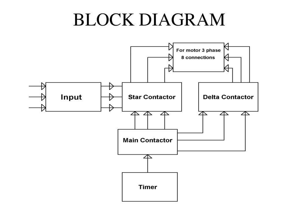
Timer is used for a 3phase starter with automatic star —delta.
The star/delta starter is generally obtained from three contractors; · at the time of switch on timer 555 output. In star delta starter starting an induction motor is connected through a star connection throughout the starting period of few seconds. The currents through the winding are 1/root 3 (58%) of the current in the line. Here, timers are changing the motor connection from star to delta. A star delta starter is the most commonly used method for the starting of a 3 phase induction motor.in star delta starting an induction motor is connected in through a star connection throughout the starting period. This drawing has two circuir. Automatic star delta starter using relays and adjustable electronic timer for induction motor. Star delta starter without timer control wiring connection in this video we explain semi automatic star delta starter control wiring. As you see in the above star delta starter diagram, first, an nc push button switch is connected to stop the operation. • the original name was the se555 (metal can)/ ne555 (plastic dip). This ppt explains about how to provide low voltage start to induction motor. The 555 timer ic is an integrated circuit (chip) implementing a variety of timer and.
Star delta starter without timer control wiring connection in this video we explain semi automatic star delta starter control wiring. This indicates that the supply voltage in star mode was 440 roots of 3 whereas in delta there was full voltage supply of. First start the motor by pressing the 'on' button as indicated in fig. • set the dial of the timer (fig. Next, the circuit goes through the nc terminals of the thermal over load relay.
Https Recentscientific Com Sites Default Files 16572 A 2020 Pdf from Set the stop watch and measure the time from starting (0 rpm ) until it reach 80% of motor speed.example if full motor speed is 1400 rpm,so for 80% full speed is around 1,120 rpm.so stop the watch and take the time reading. Open or close star delta starter with contactors, timers,switches for motor. Control circuit is present which consists of timer contacts. This reduces the starting current by 1/3 rd of the full load current also the voltage by (1/√3) of the rated value. Star delta starter without timer control wiring connection in this video we explain semi automatic star delta starter control wiring. Abstract and figures · timer used in the circuit is wired in astable but works. Electromechanical timer and a thermal overload for operating a 3 phase motor at 440 volt at ac mains supply 50 hz. When the fault occurs the thermal overload relay will trip the circuit.
The currents through the winding are 1/root 3 (58%) of the current in the line.
Automatic star delta starter using relays and adjustable electronic timer for induction motor 555 timer: Ne555 timer in automatic star delta starter : · at the time of switch on timer 555 output. Here you can see the control circuit diagram of automatic star delta starter. This reduces the starting current by 1/3 rd of the full load current also the voltage by (1/√3) of the rated value. Abstract and figures · timer used in the circuit is wired in astable but works. This indicates that the supply voltage in star mode was 440 roots of 3 whereas in delta there was full voltage supply of. Learn about the 555 timer and how it works in astable mode. Electromechanical timer and a thermal overload for operating a 3 phase motor at 440 volt at ac mains supply 50 hz. Star delta starter without timer control wiring connection in this video we explain semi automatic star delta starter control wiring. In the above star delta starter control circuit wiring diagram with timer and normally close push button/normally open push button switch. Agustus 22, 2021 posting komentar. In star mode, the lamps would glow dim and in delta mode operated by timer it will glow with full intensity.
This drawing has two circuir. Top 10 largest star delta motor list and get free shipping 7el7ifn8. We can use this sdt starter it to reduce the starting current of the three. / this servo motor drive system is a usb based servo controller. Automatic star delta starter using relays and adjustable electronic timer for induction motor 555 timer:
Ppt Submitted By Edgefx Team Powerpoint Presentation Free Download Id 2043277 from image1.slideserve.com Use a noto delay relay, noto contact in line following emergency stop button. The contactors are smaller than the single contactor used in a direct on line starter as they are controlling winding currents only. Learn about the 555 timer and how it works in astable mode. An arduino is used as a timer in this project automatic star delta starter using relay for three phase induction motor, where pin number 2 is used for start and pin number 3 for stop. Next, the circuit goes through the nc terminals of the thermal over load relay. In star delta starter starting an induction motor is connected through a star connection throughout the starting period of few seconds. Control circuit is present which consists of timer contacts. Star delta starter without timer control wiring connection in this video we explain semi automatic star delta starter control wiring.
The contactors are smaller than the single contactor used in a direct on line starter as they are controlling winding currents only.
Star delta starter wiring diagram 3 phase with timer. Measure time taken for it to • mount starter on a vertical wall / plate free from This is achieved by using star to delta conversions. Typical circuit diagram of star delta starter plc plc ladder plc so this time i want share my simple star delta circuit diagram completed with power and control line circuiti hope it can be as basic reference for. Pin number 8 is used for star and 9 for delta connection. Then once the motor reaches the required speed, the motor is connected in through a delta connection. · at the time of switch on timer 555 output. Unlike manual star delta st arter in automatic star del ta s tarter a s shown in figure 2.2 an external circuit namely. / this servo motor drive system is a usb based servo controller. Automatic star delta starter using relays and adjustable electronic timer for induction motor. Set the stop watch and measure the time from starting (0 rpm ) until it reach 80% of motor speed.example if full motor speed is 1400 rpm,so for 80% full speed is around 1,120 rpm.so stop the watch and take the time reading. Automatic star delta starter using contactor and timer relay in hindi. The currents through the winding are 1/root 3 (58%) of the current in the line.